
Automotive electronics programs grow more complex, software-dependent and densely integrated with each model year. As that complexity increases, the failure mode landscape becomes harder to map comprehensively. A single electronic control unit (ECU) may manage powertrain, safety and infotainment functions simultaneously, with each function introducing failure pathways that can interact in unpredictable ways.
Mapping those failure modes clearly means applying the same Failure Mode and Effects Analysis (FMEA) risk-scoring lens that quality and engineering leaders already use to prioritize action across a testing program. The next step is applying it specifically to the failure modes that automotive reliability testing commonly uncovers.
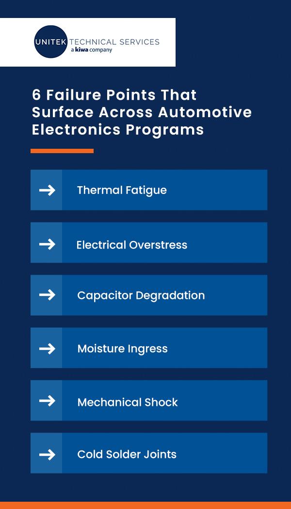
6 Failure Points That Surface Across Automotive Electronics Programs
These are the different types of failure modes that consistently surface across automotive component testing programs:
1. Thermal Fatigue
Engine bays, cabin interiors and underhood zones can expose automotive electronics to wide and demanding temperature ranges. Each power cycle generates heat and then cools the system down, driving thermal expansion and contraction throughout the assembly. Over thousands of repetitions, that movement can create micro-cracks in solder joints, particularly at the interface between the solder and the intermetallic compound layer.
Eventually, the joint can lose electrical continuity or produce intermittent faults. Research shows that engine room ECUs experience greater degradation than cabin electronics, a gap driven by wider temperature swings and a mismatch in coefficients of thermal expansion between component materials.
This failure mode often produces intermittent faults rather than clean, repeatable failures, making it difficult to detect during standard end-of-line testing. Thermal cycling and thermal shock testing are commonly used to surface these issues before a unit ships. Once a thermal and mechanical stress failure surfaces, tracing it back to its origin typically requires structured root cause analysis rather than a simple retest.
2. Electrical Overstress
Electrostatic discharge (ESD) and electrical overstress (EOS) are two distinct yet related electrical failure mechanisms that frequently occur in automotive electronics testing.
ESD occurs when a rapid, uncontrolled discharge of static electricity reaches a component. It’s particularly damaging to gate oxide layers and sensitive CMOS circuits. EOS is the broader category. It covers conditions where a component is exposed to voltage or current beyond its rated tolerance, including transient voltage spikes, load dump events or test equipment misapplication.
Both mechanisms can produce latent damage, meaning the component passes initial testing and only degrades or fails once it’s in the field. AEC-Q100 qualification requirements mandate ESD testing for every automotive IC product, typically performed using the Human Body Model and Charged Device Model test methods. Of the two failure paths, latent damage carries the higher program risk — a component that passes initial testing provides no early warning that a field failure is imminent.
3. Capacitor Degradation
Electrolytic capacitors are among the most vulnerable components in automotive electronics, prone to electrolyte evaporation and equivalent series resistance (ESR) drift over time, especially under sustained high-temperature exposure. Capacitor degradation can remain hidden during standard electrical testing while ESR climbs in the background. As that resistance increases, it can lead to voltage regulation issues, power supply instability and system-level faults that only get traced back to their source through root cause analysis.
This is particularly relevant in ECUs and power management modules, where a capacitor’s condition directly affects the stability of everything downstream. In many configurations, capacitor degradation produces no fault code at all. Validation plans that include ESR measurement or thermal soak conditioning are better positioned to identify this degradation path before it progresses toward failure.
4. Moisture Ingress
When moisture enters connectors, PCB surfaces or component housings, it can trigger electrochemical corrosion that degrades conductors and contact surfaces over time. It can also lead to dendritic growth, where conductive whiskers form between circuit traces and cause intermittent shorts. In automotive applications, moisture ingress is accelerated by temperature cycling. Seals and gaps that repeatedly expand and contract eventually let in condensation.
Connector interfaces most often see this failure mode, as mechanical seams create natural entry points for moisture. Per AEC-Q100, the following qualification test categories can be used to surface this risk before it reaches the field:
- Temperature-humidity bias testing holds components at elevated temperature and humidity while under electrical bias to accelerate corrosion and dendritic growth over a compressed timeline.
- Autoclave and HAST testing use pressurized, saturated steam environments to expose moisture-related weaknesses faster than standard humidity testing alone.
5. Mechanical Shock
Road vibration, engine harmonics and shock loading from potholes and curb strikes create a mechanically demanding environment, where stress accumulates over time and induces fatigue in solder joints, component leads and connector pins. Connector fatigue develops from repeated micro-motion at the interface. This micro-motion wears down contact surfaces, gradually increasing resistance until the connection produces intermittent or fully open circuits.
Body control modules, ABS sensors and underhood electronics face this risk most directly, as they sit close to sources of continuous vibration. Mechanical shock and vibration testing are standard methods for assessing this risk. However, resulting failures are frequently misdiagnosed, since the fault often only presents itself under dynamic load conditions and disappears once a unit sits still on a bench.
6. Cold Solder Joints
Cold solder joints are assembly faults that exist from the moment of manufacture. They may fail immediately or present as early-life or intermittent faults soon after. A cold joint forms when solder doesn’t fully wet the component lead and the PCB pad during reflow, resulting in a high-resistance or mechanically weak connection rather than a solid bond.
Other assembly faults follow a similar pattern, including missing components, misaligned placements and solder bridges that short adjacent pads together. Because these defects originate during manufacturing, upstream verification plays a larger role than downstream testing.
How FMEA Turns a Failure Mode List Into a Risk-Scoring Framework
Identifying an electronic component failure mode is only the first step in determining how much risk it creates for the program. The second step is knowing which ones actually deserve engineering attention first, and that’s the problem FMEA is built to solve.
This kind of failure mode analysis assigns a risk score to each failure mode across three dimensions:
- Severity: How serious the effect is if the failure reaches the customer
- Occurrence: How likely the underlying cause is to happen
- Detection: How likely current testing is to catch the failure before it ships
Traditionally, these three scores are multiplied to form a Risk Priority Number (RPN). The higher the RPN, the more urgently the failure mode demands a testing or design response. That said, RPN has a well-documented flaw. For example, a Severity 10, Occurrence 2, Detection 4 failure scores an RPN of 80. A Severity 3, Occurrence 10, Detection 4 failure scores 120, which means a less severe failure can appear more urgent because the math favors frequency over consequence.
The AIAG & VDA FMEA Handbook, updated in 2019, addresses this by replacing RPN with Action Priority (AP), a three-tier High, Medium or Low rating that weights Severity more heavily and prevents that kind of mathematical artifact from driving prioritization decisions.
Many automotive programs still discuss RPN day-to-day out of habit, but the current AIAG standard runs on AP. DFMEA and PFMEA remain core deliverables within APQP and PPAP processes regardless of which scoring system a program uses.
Applied to common failure modes, thermal fatigue in an engine room ECU typically carries high Severity, since a lost connection can affect powertrain or safety functions. Combine that with the moderate-to-high Occurrence from routine thermal cycling, and the failure mode may push toward a high Action Priority when Severity, Occurrence and Detection ratings align.
ESD-induced latent damage plays out differently. Its Severity is also high, since a field failure can create warranty exposure, production disruption or additional supplier-quality review, while Detection tends to be poor because a component that passes the initial test can still carry hidden damage. That low Detection score is what elevates the failure mode’s priority, even when Occurrence looks manageable, and it’s exactly the scenario AP was designed to catch.
What High-Priority Failure Modes Demand From Your Testing Program
Once FMEA scoring surfaces which failure modes carry the highest risk, the next consideration is whether the validation program has the testing coverage to catch them. For automotive electronics specifically, that coverage looks different depending on the failure mode in question.
ECU Validation
ECU failures, whether software regressions, logic errors or communication faults, carry high Severity scores under almost any FMEA, since they tend to directly affect safety-critical and powertrain systems. Catching them necessitates more than standard functional testing. ECU validation requires Hardware-in-the-Loop (HIL) and Software-in-the-Loop (SIL) simulations that replicate the full system context, including fault conditions and edge cases, to confirm the ECU behaves correctly under conditions a static bench test simply can’t reproduce.
Automotive ECUs also communicate across Controller Area Network (CAN), Local Interconnect Network (LIN) and FlexRay protocols. Integration-level failures at that protocol layer, including timing errors, message frame corruption and node dropout, require technicians with specific protocol expertise to identify accurately. Validation plans that include protocol-level checks are better positioned to catch these issues, which is why thorough validation depends on a team built specifically around automotive protocols and ECU behavior.
Environmental and Stress Testing
Many wearout failure modes, including thermal fatigue, moisture ingress and capacitor degradation, are latent by nature. Rather than producing an immediate, obvious failure, they develop over time under specific conditions. Environmental and stress testing compress those conditions into a validation timeline short enough to act on before production scales.
The following AEC-Q100 qualification test categories may apply to automotive IC qualification, depending on the device and package type:
- Thermal cycling and thermal shock tests surface solder joint fatigue by repeatedly cycling components through extreme temperature swings.
- Temperature-humidity bias and HAST tests reveal moisture ingress and corrosion risk by exposing components to elevated humidity and, in HAST’s case, pressurized steam.
- Mechanical shock and vibration testing tests surface connector fatigue and vibration-induced solder failures by replicating the mechanical stress of road use.
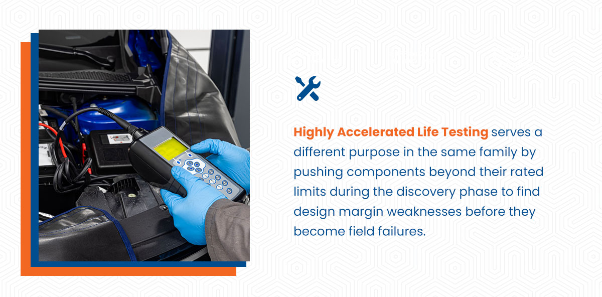
Highly Accelerated Life Testing serves a different purpose in the same family by pushing components beyond their rated limits during the discovery phase to find design margin weaknesses before they become field failures. For ECUs and other electrical and electronic systems, this testing can also support the broader ISO 26262 functional safety case that a program builds alongside IATF 16949 quality management expectations.
How Failure Mode Analysis Supports Root Cause Analysis
Failure mode analysis identifies what went wrong and how urgently it matters, but root cause analysis explains why the issue happened in the first place. An FMEA entry showing high Severity and high Occurrence for thermal fatigue confirms the failure exists and matters, but it doesn’t say whether the root cause is a design margin issue, a materials change, a supplier process deviation or a gap in test coverage.
Without closing that loop, the same failure mode tends to recur, regardless of how well it was scored the first time. This is where root cause analysis tools like 5 Whys, 8D and Fault Tree Analysis translate an FMEA finding into a causal investigation. Once a cause is confirmed, supplier quality engineers build supplier engagement plans and corrective action plans around it.
There are corrective and preventive action processes that verify that a fix actually works and that preventive controls are in place before the next production cycle begins. FMEA scores can also inform risk-based inspection planning, directing inspection frequency toward the failure modes that a program’s data says matter most.
Start the Conversation With Unitek Technical Services

Thermal fatigue, ESD, capacitor drift, moisture ingress, connector fatigue and cold solder joints score differently in an FMEA, but they share one challenge: identifying coverage gaps that could allow latent failures to reach the field.
Unitek Technical Services a Kiwa Company partners with automotive electronics organizations to help identify testing coverage gaps, manage risks earlier in the production cycle, and simplify the supply chain process so your team can stay focused on core operational goals.
Our team supports product verification through source inspections, the FAI and pre-encapsulation checks, with inspection scheduling and results captured through Launchpad when applicable. We can also provide technical support for APQP and PPAP planning, including DFMEA and PFMEA, ECU test execution involving HIL, SIL, and protocol-level checks on CAN, LIN, and FlexRay, and root cause analysis when a failure needs to be traced to its source.
Contact us today to discuss your needs and assess your program’s coverage.